| All returns accepted | ReturnsNotAccepted |
|---|---|
| Model | 210 |
| MPN | 210 |
| Brand | Greenlee |
| Type | Resistance Fault Meter |
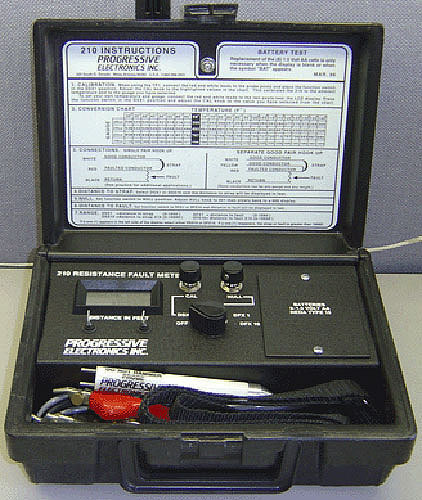
Check the listing for details. NEW Progressive Electronics/Greenlee 210 Resistance Fault Meter. Condition: New – Open box. Listed at 149.99 USD. NEW Progressive Electronics/Greenlee Model 210 Resistance Fault Meter Comes with what you see in the pictures. If you don't see it you probably wont get it. Specifications are from Progessive Electronics and may vary slightly due to upgrades, options, or revisions this unit may or may not have. Comes with a set of batteries and the tiny manual that we received with the unit which includes: General, Description, Operation, Special Applications, Maintenance, Warranty information. List Price was: $597.42 Brand New. General Information: The Model 210 is a resistance fault meter that digitally displays distance to a fault or strap. It is designed for use on telephone cable and service wire by installation, maintenance, loop and cable repair technicians. The Model 210's simple operation allows even inexperienced telephone trouble shooters to be successful in locating high resistance shorts, grounds and crosses while in the presence of foreign voltages. The Model 210 is internally preset to a standard temperature value, or for more precise readings, the temperature probe (included) should be used. Description: The Progressive Electronics Model 210 is powered by eight (8) "AA" cells with a battery life of approximately 100 hours. The unit is housed in a durable case measuring 7.5" x 3.5" x 10" and weights 2 lbs. 14 oz. (Does not include shipping weight or dimensions) The temperature probe, TP-1 Measures 5.5" in length and 5/8" diameter and weighs less than 2 oz. The tip is constructed of aluminum for thermal conductivity, the body is made of high impact plastic and the two posts are stainless steel. The red and white test leads are connected to the posts during the calibration procedure. Calibration: The Model 210 is calibrated to any given gauge at 68 degrees Fahrenheit by connecting the red and white test leads to the two posts located under the LCD display meter (Polarity is not a factor). For precise readings, the temperature probe (TP-1) should be used. Connect the red and white test leads to the two probe posts (Polarity is not a factor). Place the probe in the ground as close to the cable depth as possible or in aerial applications, let the TP-1 adjust to the ambient temperature for a few minutes. If the cable is in the sun, wrap the temperature probe with black tape to allow for increased temperature inside the cable. The temperature probe allows the 210 to be calibrated to a known gauge at a known temperature. Turn the control knob to the DSx1 position, then rotate the calibrate (CAL) knob to the corresponding value assigned to the gauge of wires as follows: Gauge: 19 Value: 1566 Gauge: 22 Value: 787 Gauge: 24 Value: 493 Gauge: 26 Value: 308 With the Model 210 calibrated to the correct temperature and gauge, disconnect the red and white test leads from the posts of the temperature probe and connect all the clips to the conductors under test. Distance to Strap: Once the test leads are connected to the conductors under test and the strap is in place, the distance to strap reading will be displayed in feet. If a one (1) appears in the left side of the meter, place the function switch in the DSx10 position. The new reading should be multiplied by 10. If a one (1) reappears, the distance to strap cannot be read (over 19999 feet). If you know that the distance to the strap is less than 19999 feet and a one (1) is displayed, there is a bad connection at the strap or at the red and white test leads. Note: Distance to Fault measurement can still be read accurately up to 19999 feet even if Distance to Strap is over ranged (19999) but is known to be under 100000 feet. NULL: After reading the distance to Strap, place the function switch in the "NULL" position. Adjust the nulling knob so that the display reads 001 then slowly back to 000. (Clockwise adjustments give positive readings and counter-clockwise adjustments give negative readings.) If the meter will not null (000), the resistance is too high to read. High resistance faults (over one mega-ohm) can be readable by adding battery in series with the black clip. When measuring a ground fault, connect a 45-90 volt battery negative to the black clip, and battery positive to the ground. When measuring a short, connect battery negative to the black clip and battery positive to the other side of the pair. The added battery will make the resistance fault appear heavier to the 210. If the set nulls, the fault can be measured. Distance to Fault: Place the function switch in the DFx1 position and the display will indicate distance to fault. Again, if a one (1) appears, change the function switch to DFx10 position. The new reading should be multiplied by 10. If a one (1) reappears, the distance to fault is out of range (over 19999 feet). Note: Because of the accuracy of the Model 210's ability to read through battery and high resistance trouble, it is not necessary to include a strap to fault reading. To get this measurement, simply subtract the distance to fault from the distance to strap. Temperature Conversion (Special Applications): If it is impracticable to use the Temperature Probe (TP-1) and the temperature of the cable is known, calibrate the Model 210 by using the Conversion Chart (below). Connect the red and white leads to the two posts located under the LCD display and dial the CAL knob to the corresponding value obtained from the chart. The temperature chart will allow the operator to program in a known gauge at a known temperature for extremely accurate measurements. Conversion Chart Temperature (°F) Gauge 26 GA. 24 GA. 22 GA. 19 GA.30336538858 170935333532848 168940329526838 166945325520828 165050321514819 163155318508810 161260314502801 159465310496792 1577 68 308 493 787 156670307491783 156075303486775 154380300481766 152785297476758 151190294471750 149595291466742 1479100288461735 1464105285456727 1449110283452720 1435115280447713 1420120277443707 1406125275439700 1393130272435693 1380135269431687 13671402664266801354 Load Coils: Load coils measure from approximately 3.6 to 4.2 ohms. For an approximate distance when measuring through a load coil, subtract: 95 feet when measuring 26 gauge 150 feet when measuring 24 gauge 250 feet when measuring 22 gauge 470 feet when measuring 19 gauge Because the resistance of load coils vary considerably, any allowances or conversion factors cannot be relied upon for precise measurements. The presence of load coils in the section of cable under test will cause the locator to give readings greater than the actual distance. To insure precise measurement, it is always best to isolate the cable between load coils. For Domestic Customers: Packaging, handling, and order processing included in shipping in all domestic shipments as quoted by the shipping calculator. For International Customers there is a $10.00 minimum for packaging, handling, and order processing. International shipping to be determined by destination. Prior to shipment I will need to know the following information (filled out on a form that I will send you) for International Customers or Packages/Freight being Forwarded internationally. International customers may also be subject to a freight forwarder form if applicable.: (1) Are you the end-user of this item? (2) If you are not the ultimate end-user of the item, please state the ultimate end user's name. (3) What is the ultimate country destination? 05/06/04
You may also like