| Return shipping will be paid by | Seller |
|---|---|
| All returns accepted | Returns Accepted |
| Item must be returned within | 30 Days |
| Refund will be given as | Money back or replacement (buyer's choice) |
| MPN | NP2-ES |
| Brand | Northstar Loop Detectors |
| Model | Northstar NP2-ES |
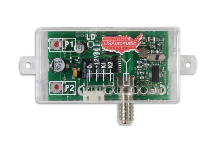
Check the listing for details. Northstar Vehicle Detector - NP2-ES Single Channel – Dual Output Plug-In Vehicle. Condition: New. Listed at 101.95 USD. Northstar Vehicle Detector - NP2-ES Single Channel – Dual Output Plug-In Vehicle Detector Northstar Vehicle Detector - NP2-ES Single Channel – Dual Output Plug-In Vehicle Detector Model NP2-ES Features:• Plug-in compatible with many of today’s gate operators.• 4 selectable Sensitivities.• 4 selectable Frequencies.• Wrong voltage protection.• Separate Power/Fault and Detect Indicators.• Automatic Sensitivity Boost.• Power Supply requirement 10 to 30 Volts AC or DC, 5mA nominal. The Northstar Vehicle Detector - NP2-ES Single Channel has been specifically designed and engineered for use in the Parking/Access Control industries and is designed for plug-in compatibility with many contemporary gate operator designs. With standard operations including compatibility with all radio controls and more, the Northstar Vehicle Detector - NP2-ES Single Channel covers your low power, plug-in detection needs. The Northstar Vehicle Detector - NP2-ES Single Channel wide inductance range allows for use with small loops sometimes found in the Parking/Access Control industries (for recommended loop sizes please consult the Northstar Loop Information Guide). Separate indicators for power/fault and detect output provide for quick visual verification of proper operation. Loop diagnostics are easily viewed with the front panel power/fault indicator. Reliable operation and long field life are key engineering goals in every Northstar product. NP2-ES Specifications Front Panel Selections Sensitivity – controlled by front panel DIP switch. • 0 = Low sensitivity • 3 = High sensitivity Medium sensitivity is used for most applications; this is a setting of 1 or 2. Always use the lowest sensitivity setting that detects the desired vehicles. Frequency – four separate settings controlled by front panel DIP switches. • 2+1 = High • 2+0 = Medium High • 1+0 = Medium Low • 0+0 = Low Reset – front panel reset performs a hard reset of the detector. Internal Switch Settings: Call Delay – select from delay off and 2 second delay. Call Extend – select from extend off and 5 second extend Permanent Presence – select from 60 minute and permanent presence. Outputs: Detect Output is fail secure, loss of power does not cause a detect output to be placed. Factory Settings • Set to High frequency • Set to Medium Low sensitivity (1) Specifications: Output Rating: Solid State both Detect and Fail. 30mA Maximum current sink. Outputs are protected from over-voltage or polarity reversal. Power: 10 to 30 volts AC or DC, 5mA nominal. Inductance Range: 20uH to 1500uH. Temperature Range: -30 F to +180 F. Lead-In Length: up to 2500 ft. with proper lead-in and loop. Mechanical: 2.4” H x 2.25” D x 0.8” W. Supply Voltage – incorrect voltage supplied to the unit will not result in damage, the unit will simply not operate until correct voltage is supplied. No fuses need to be reset. Indicators – front panel indicators: Power/Fault - Green, solid with correct power supplied. - Flashes during a fault condition. - Fault flash sequence: Single flash and pause = Open Circuit Loop, Double flash and pause = Shorted Loop. Detect - Red, solid during detect. Power Saving Mode: While in normal operation with no fault indication, the Green LED will extinguish after a period of 2 minutes. A power interruption or reset will re-illuminate the Green LED. Sensitivity Boost – automatic during detect except in the highest sensitivity setting (3). Connector: – 10 position Molex Type 09-48-1104 L NP2ES-Rev C Pin # Function 1 Loop 2 Loop 3 Power – 10 to 30 V AC/DC 4 Not used 5 Not used 6 Fail output 7 Fail output 8 Detect output 9 Power – 10 to 30 V AC/DC 10 Power common Note: The above connections are shown with correct power supplied and no vehicle present. Payments & Returns Policy
You may also like